Today we are going to learn how to communicate with the ESP8266 module through the serial (UART) connection using AT commands.
In the previous post we learned how to connect the ESP8266 to a computer and test the serial and WIFI connection. If you need help hooking up your ESP8266 module take a look here: ESP8266 ESP-01 testing - Part 1
AT commands
Serial communication with the ESP8266 is done using AT commands. If you are not familiar with AT commands, they are instructions used to control modems. The ESP8266 is controlled the same way as a modem or GPS module. An instruction (or command) request is sent to the device to perform an action that once evaluated is executed (or not) and a "response" is given in return. The ESP8266 accepts many AT commands but today we are only going to use some of the most common ones. A full list of ESP8266 AT commands is provided at the end of this post.The board used in this tutorial uses the stock firmware version .9.0.2 (00180008902) from AI-Tinker.com. Different firmware versions may behave differently. The AT commands list has also been updated since these boards where launched. If you are using a board with older firmware version and/or older AT commands version, newer AT commands will not be recognized! Like with firmware, the ESP8266 board AT list can be updated.
Let's get started!
Test AT startup
The first command we are going to send to the ESP8266 board is simply AT. It's used to test the startup function of our ESP8266 module. In RealTerm:
- Click the Send tab.
- Type AT in the first textbox.
- Check the +CR and +LF.
- Press the Send ASCII button.
The ESP8266 board should respond with an OK message. This tells us the command was received and the serial communication is ready and working.
View version information
Now lets find out what is the firmware version of our ESP8266 board. Send the AT+GMR command.
This board uses firmware version .9.0.2 (00180008902). This is an old firmware version.
Note: the version information displayed depends on the firmware running on the board. Newer firmware versions display the firmware version and the AT commands version.
Change baud rate
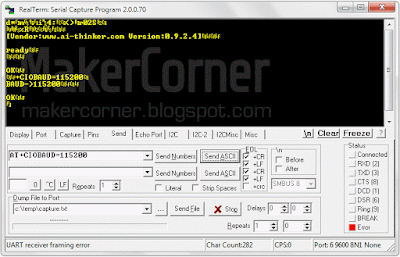
Lets change the ESP8266 baud rate, or the speed of the serial communication. Let's try 115200 baud. Type AT+CIOBAUD=155200 and press the Send ASCII button. The ESP8266 should output the following text which confirms the new baud rate was accepted:
Notes:
Newer boards accept two sets of serial parameters: AT+UART_DEF (default params, saved on the board memory) and AT+UART_CUR (current params, not saved).
Now the ESP8266 serial interface is running at 115200 baud. Since we changed the baud rate in the ESP8266 module we must also change the baud rate in RealTerm to 155200!
The new baud rate was set and stored in the ESP8266 memory. From now on, every time the board is started or restarted it will default to 115200 baud rate.
We can also ask our ESP8266 module what the baud rate is. To do this we send the command AT+CIOBAUD?
Other AT commands you might want to test:
AT+RST – Restart module;
AT+RESTORE – Factory reset.
Wi-Fi related AT commands
Before trying out WiFi commands we should get familiar with the different WiFi modes. As we know, the ESP8266 supports three modes: station mode, softAP (virtual access point) mode and station mode + softAP mode. In station mode the ESP8266 works as a network device and can connect to an existing wireless network (router). In softAP mode the ESP8266 behaves as a wireless router and can be connected to by network devices.When operating in both modes (softAP + station mode), the ESP8266 can act as network repeater.
Set WiFi mode
The default ESP8266 WiFi mode is softAP (2). To know
what mode your ESP8266 module is in, send the command AT+CWMODE?
According
to what WiFi mode the ESP8266 is on it will respond with 1 : station
mode, 2 : softAP mode or 3 : softAP + station mode.
To set to a particular WiFi mode send AT+CWMODE=X, where X is the mode you want to set.
To use the next WiFi
commands the ESP8266 must be in mode 1 or mode 3, so change to station mode (mode 1), sending AT+CWMODE=1.
Note:
AT+CWMODE will not be recognized by boards with firmware from Espressif, use AT+CWMODE_CUR or AT+CWMODE_DEF instead.
Get list of available WiFi access points in our location
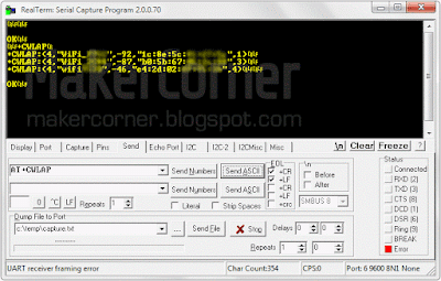
Type and send the command AT+CWLAP. The ESP8266 will scan the WiFi frequency range and list all the access points in range. Each line item consists of the security level of the AP, network name, signal strength, MAC address and WiFi
channel.
Security Modes:
| 0 | Open |
| 1 | WEP |
| 2 | WPA_PSK |
| 3 | WPA2_PSK |
| 4 | WPA_WPA2_PSK |
Note:
If the you get an AT+CWLAP ERROR set the ESP8266 to station mode or softAP + station mode.
Join access point
To join an access point we can use the command AT+CWJAP="SSID","Password".SSID is the
After a few seconds the ESP8266 should respond with OK if successful or FAIL if unsuccessful. After the board joins an access point, it will store that AP SSID and password and automatically join that access point every time the board starts up! To stop this, simply disconnect from the AP before powering of the board.
Note:
This command has been deprecated. If your board uses firmware from Espressif use AT+CWJAP_CUR or AT+CWJAP_DEF instead. See the Espressif ESP8266 AT commands list for details.
Disconnect from AP
To disconnect our ESP8266 from an access point simply send the AT+CWQAP command.
Documentation and tools:
Download RealTerm here.
Download AI-Thinker AT commands list here (unofficial).
Download Espressif ESP8266 AT commands list here.
Buy the Parts:
Buy the ESP8266 Wi-Fi from Banggood
Buy the ESP8266 Wi-Fi from Dealextreme
Buy the USB to Serial Adapter from Banggood
Buy the USB to Serial Adapter from Dealextreme


No comments:
Post a Comment